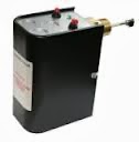
Here's how things looked before our make-over:
Monday, August 3, 2015
Latest boiler room makeover.
This is a recently completed boiler system project that involved significant repiping and improvements to incorporate a new master bath radiant floor circuit and performance improvements. A buffer tank was added to eliminate boiler short-cycling and outdoor reset was added to the radiant floor circuits (master bath, family room and first floor bath) to prevent an over-temp condition. Variable speed circulators were added to reduce pumping costs and manifolds were added with zone valves and controllers for individual circuits. Slab sensors were added to the master bath and family room. Piping improvements were made to give the owner more predictable control over room and floor temperatures. The improvements will make this home more comfortable while saving fuel.
Sunday, March 30, 2014
Some Things I’ve Learned in 30 Years of Business
This week marks thirty years since the incorporation of my
business. I’m not a particularly nostalgic person so I hadn’t been thinking
much about it. I just realized last week that April 1st was coming
up (the day my business was formally created) and, wow, has it really been 30
years?
That got me thinking about where I’ve been, where the
industry has been, what I’ve learned and where things are going.
My business has had different iterations through the years.
From d-i-y plumbing retail, new home construction, service, remodeling, HVAC,
and my current passion and recurring theme from the very beginning — hydronic
heating.
I’ve always had a desire to learn new things and stay on top
of the latest industry trends, albeit with a healthy dose of skepticism toward
flash-in-the-pan ideas. In some ways, keeping up with the technology is the
easy part. It’s the other life lessons —learned through experience — that have really
made things interesting.
I’ve seen some things I’d rather forget — like the squalor
of a neglected elderly man’s home, or a basement, so full of bees, that the
100-watt light bulb at the bottom of the stairs looked like a night-light.
And I’ve been involved in many memorable projects — from
landmark restorations to Homearama. From Habitat For Humanity to the Shepherd
Home.
But people and relationships are what’s most rewarding about
the last 30 years. I truly consider most of my clients to be friends. Friends
that respect each other and are loyal to each other. Friends that want each
other to succeed and live healthy, happy lives.
Thank you to all my friends. Thank you for allowing me to be
part of your lives and welcoming me into your homes.
Hydronically yours,
Wayne
Sunday, March 23, 2014
Punch Out the Holes
It was time for a new shower curtain in our bathroom. It’s a
simple enough task. But as I started to hang the curtain on the first hook, I
realized that the holes in the top of the curtain where the hooks are inserted
are not punched out. Oh, they’re outlined and perforated, ready for punching —
but they still need to be punched out.
I didn’t think much of it on the first hole, but by the time
I was on the sixth hole I was starting to wonder, why wouldn’t the manufacturer
finish punching out the holes? Are there really people who hang their curtain
without using the holes? And would those people really object to the aesthetics
of holes where they didn’t need them?
By the twelfth hole my arms were starting to ache and I was
getting aggravated with the whole lack-of-hole thing. Why leave out the holes?
Why make more work for your customers? Are you really saving that much in the
manufacturing process by eliminating the hole-penetration step?
Maybe the curtain manufacturer cares. Maybe they don’t.
Either way, I’ll probably never take the time to let them know. I’ll blow it
off as not worth the effort.
It got me thinking about my clients. I wondered if maybe
there are holes I’m not punching out in my process. Are there things I’m
leaving undone that create little aggravations for you?
I try to cover all the bases. That’s why I perform heat loss
calculations, and ask you how you use your heating system, and clean up after
myself, show up on time, return your phone calls and emails, and do a multitude
of other on- and off-the-job tasks intended to soften the impact of what I’m
doing on your everyday life.
But I still wonder if I’m leaving some holes unpunched. Is
there something I’m not doing, that despite my best efforts is even a small
aggravation for you? Something that causes you inconvenience?
We all love to hear praise, and I’m no different. But
without criticism how are we to improve? And I do want to improve.
So, please, tell me what aggravates you. I’ll listen. I
promise. And then I’ll punch out the holes for you — whatever those are.
Hydronically yours,
Wayne
Sunday, March 16, 2014
The Truth About Troubleshooting
-->
Most times, when things go wrong with your hydronic system
(or any mechanical or electrical system) there’s a clear reason for the
failure. Experience tells me where to look for the most obvious source of the
problem in order to make a quick repair and get things up and running again.
But every once in a while a problem crops up that doesn’t
lend itself to a quick diagnosis. Maybe it’s something I haven’t seen before or
there are unique conditions affecting the equipment in unexpected ways.
I like to look at these situations as opportunities — to
learn something new, to challenge my troubleshooting skills and to show you how
committed I am to making things right. That’s not to say these opportunities
are without their challenges.
It takes hard work, research and focus. Getting to the root
cause and fixing the problem once and for all requires a complete understanding
of what went wrong. And, more often than not, it takes patience. Patience on my
part — and yours.
It’s relatively easy to throw a bunch of parts at a failed
system and get a quick fix. But unless we take a systematic approach to
troubleshooting, we’ll never know the true cause — and therefore won’t be sure
it can’t happen again.
I’ve found the best way to get to the true cause is to make
one change at a time and measure the effect of that change. That way I can be
confident that the final fix will be permanent, because I’ve truly gotten to
the root cause of the problem.
You play a big part in the troubleshooting process, too.
Your feedback and observations of system performance are critical. So is your
patience. It will likely take several visits and a fair amount of communication
to get to the bottom of a stubborn issue. But together, we’ll get it done. And
we’ll both be better off for having worked it through systematically.
Hydronically yours,
Wayne
Hydronically yours,
Wayne
Sunday, March 9, 2014
An Ideal Heating/Cooling System for Your Small Addition
Last week I explained why the use of a ductless mini-split heat pump
system as the sole source of heating and cooling is not the right application
for the small (less than 1000 sq. ft.) addition. In order to properly size for
the heating load on colder days, you’d be left with grossly oversized cooling
capacity. And that will cause the heat pump to short-cycle when cooling on any
day except for the very warmest. This short-cycling will result in less
comfort, less efficiency, increased maintenance and shorter equipment life. Not
good. After all, who wants to stress about their heating/cooling system.
You want to be comfortable all year long. If you want to expand your
home with a small addition, I recommend ductless mini-split heat pumps for cooling in
applications where the primary heat is supplied by another source — like
radiant floor, finned-tube baseboard, radiant panel or hydro-air. That way I
can size the cooling portion for ideal comfort and the heating portion of the
heat pump can be used as a backup heat source if the main heat source is down
for maintenance.
But now there’s an exciting new technology coming to the market. It
combines the best of variable-speed compressor heat pump technology with hydronics
to provide super high-efficiency performance with the awesome comfort of
radiant heat and central cooling.
An air-to-water heat pump is the heart of this technology. During
heating season it extracts heat from the outdoor air and transfers it to water using
an indoor heat exchanger. In the cooling season, the process is reversed —
indoor heat is transferred (via the same heat exchanger) to a refrigerant and
expelled outdoors by the heat pump.
Since the heat pump has a maximum heating output temperature of
approximately 120˚F, it’s a perfect match for low-temperature radiant —
thin-slab, above-floor tube and plate, walls, ceilings, panel radiators and
some types of finned-tube baseboard. This is the most comfortable heat around.
To cool the air, a pump circulates water (chilled by the heat pump)
from the heat exchanger through a cooling coil located in an air handler. This
distributes cooled and dehumidified air throughout your addition. If the design
of the addition permits it, a standard air handler with the familiar ductwork
can be used. But if equipment space is at a premium, a high-velocity mini-duct
system with its 2” diameter ducts may be a better fit.
The efficiency of an air-to-water heat pump is rated in terms of its
Coefficient of Performance (COP). COP is a ratio of the amount of heating (or
cooling) produced to energy consumed. It’s not unusual for a variable-speed
air-to-water heat pump to have a published COP of over 4.0 and an average COP
of 2.7 to 3.0. In simple terms, for every one unit of energy consumed, the heat
pump can produce almost three units (annual average) of heating or cooling. The
only system more efficient than that is a geothermal system. (More on that
comparison in future installments.)
Even though some of these heat pumps are advertised to operate in
outdoor temperatures down to -4˚F, when the outdoor temperature drops to about
20˚F, the cost of energy input increases to the point where an alternate heat
source is more efficient. A separate gas- or oil-fired boiler can provide a
backup heat source for the coldest days as well as domestic hot water (DHW)
production year-round. And if the main part of the house is hydronically
heated, the air-to-water heat pump and the existing hydronic system are a match
made in heaven!
But even if you need a backup/DHW boiler, the incredible efficiency of
the air-to-water heat pump will offset the higher initial equipment cost with
fuel savings in just a few years.
If there’s a small addition in your future, consider an air-to-water
heat pump with radiant heat and chilled-water cooling as a renewable-energy
alternative that pays for itself.
Heidronically yours,
Wayne
Sunday, March 2, 2014
Ductless Mini-Split Heat Pumps and the Small Addition
The popularity of ductless mini-split heat pumps has grown
tremendously in recent years. They’re a great way to add cooling to a
hydronically heated home because they don’t need bulky ductwork. But like many new
things, there’s a tendency to apply them to as many situations as possible,
including some that they may not be well suited for. One such misapplication is
as the sole heating and cooling source for a small addition.
Ductless mini-split heat pumps are usually an air-to-air
heat pump — meaning it takes outside air and strips it of its heat value and
transfers that heat to your home to provide space heating. For cooling, the
cycle is reversed — it pulls the heat out of your house and expels it to the
outdoors. You could think of a heat pump as an air conditioner that’s capable
of working in reverse.
Heat pumps are nothing new, but the configuration of the
ductless mini-split is. The condensing unit is located outdoors and a
refrigeration lineset, small drain and wiring are run into your home through a
3˝
opening in an outside wall. They supply the indoor unit, which is usually
mounted high on a wall and contains the blower and indoor controls. Ductless
mini-splits are incredibly quiet (inside and out) and efficient.
I’m often asked to design a heating and cooling system for a
small addition to an existing home (less than 1000 sq. ft). The first thing I
look at is the capacity of the existing system to handle the addition’s extra heat
and cooling load. More often than not, especially with forced air, the existing
system can’t do the job. The system in a hydronically heated home can almost
always handle the additional heating load but it obviously can’t provide
cooling.
That usually leads to someone suggesting a ductless
mini-split heat pump for heating and cooling the addition. It’s tempting,
because it’s a relatively easy, quick and inexpensive installation. And here’s
where the misapplication comes in. As an example, let’s apply a ductless
mini-split heat pump to a typical 700 sq. ft. master bedroom, bath and laundry
addition.
An addition like this would typically have about a 14,000
Btu/hr heat load on the coldest day of the year (considered 0˚F in the
Rochester, NY area). It would also require just under 1 Ton (12,000 Btu/hr) of
cooling on the warmest day of the year (considered 90˚F in this area). Both
design loads would keep the indoor temperature at 70˚F.
Now, when sizing a heat pump, you size for the greatest load (heating
or cooling) so you can be sure there’s enough capacity for both seasons. In our
example case, as with most applications in this climate, the largest load is
the heating load. So wouldn’t logic dictate that we’d need a heat pump rated
for 14,000 Btu/hr? Not so fast.
We also need to consider the fact that as the outdoor temperature
drops, so does the efficiency of the heat pump. In fact, even though some of
the newer models are capable of providing heat down to an outdoor temperature
of -4˚F, at those temperatures their heat output drops to near 50% of rated
capacity. So now we realize that we need to DOUBLE the capacity of the heat
pump to have any chance of maintaining our 70˚F indoor temperature on a 0˚F
day.
That means we’re looking at installing a heat pump with a 28,000
Btu/hr minimum capacity, which actually works out fairly well, because heat
pumps come in a 2-1/2-Ton size (30,000 Btu/hr). So now that we’ve decided that
we need a 30,000 Btu/hr unit for heating, let’s see how that works for the
cooling side.
Remember, the cooling load is 12,000 Btu/hr on the warmest days
(90˚F). And there’s a 30,000 Btu/hr capacity. Simple math tells us that on even
the warmest days, our heat pump is oversized (for cooling) by 250%. And, as
you’ve heard me preach before, in cooling (and heating), bigger is not
necessarily better.
Most of the better ductless mini-split heat pumps these days use
inverter technology to modulate the compressor speed, which tailors the output
to the load. With our example, the compressor would modulate down to 40% of
capacity on the WARMEST day. That means that on a milder day it may need to be
operating in the single-digit-capacity numbers. The problem arises when the
compressor is only capable of modulating down to 30% of capacity, meaning that
anything less than 75% of the maximum cooling load (in our example) will be
asking the heat pump to work below its minimum capacity — which will be the
bulk of the cooling season!
When a heat pump is asked to work in a range below its minimum
capacity, it will short-cycle and, as a consequence, fail to properly
dehumidify. We’ve discussed short-cycling and its consequences before — less
comfort, less efficiency, increased maintenance and shorter equipment life.
For this example addition, the ductless mini-split “kind of” does the
job. It can either do an acceptable job of heating with not-so-good cooling, or
an awesome job of cooling with unacceptable heating performance.
So if a ductless mini-split isn’t the answer to heating and cooling
your small addition, what is? Be sure to check next week’s Heidronics blog post
for the answer.
Heidronically yours,
Wayne
Labels:
ductless mini-split,
efficiency,
heat pump,
hydronic,
noise,
small addition,
variable-speed
Sunday, February 23, 2014
When More Power Isn’t Always the Winner
-->
designed to operate on a pressure difference. Others operate on a temperature
difference. But either type delivers just the flow necessary to heat the space,
and either will consume much less electricity to accomplish the same results as
compared to a bigger pump.
Wayne
The Daytona 500 is all about speed and power and getting to
the finish line first. Hydronics is basically the opposite — but you’d never
know that from the way most hot water heating systems are installed these days.
Historically, North American hydronic designers and
installers have specified and installed circulating pumps that pump more water
and use more power than what is actually needed. It’s called “over-pumping.” And
if a system underperforms, the first reaction of many technicians is to install
a bigger, more powerful pump. But this almost never solves the problem.
It’s a chicken vs. egg thing. Installers either don’t have
the knowledge or won’t take the time to calculate the pumping requirements for
the system, and wholesalers don’t stock more than a few different pump models.
I’ve heard installers justify their pump choice by the “bigger is better” mentality.
And wholesalers have told me that they’d stock a wider variety of pumps but the
installers aren’t asking for them. That’s a shame.
In hydronics, like stock car racing, the object is to go
round and round until you cross the finish line and meet your goal. But unlike
stock car racing, the winner in hydronics gets there with as little effort and
speed as possible. The goal is delivering the right amount of heat from the
boiler to the heat emitter (radiator, radiant floor panel or baseboard heater,
for example). Pushing the water faster doesn’t make that happen any better. It
just wastes energy!
Over-pumping can also create a condition known as velocity
noise, which is caused by the water traveling too fast through the pipe and
fittings. It can also cause erosion corrosion — a wearing away, or eroding, of
the pipe wall due to the scouring action of high-velocity water flow.
But there’s hope. A new generation of circulators uses
variable-speed technology and highly efficient electronically commutated (ECM)
motors to vary their output to the specific needs of your system. If a zone
valve closes, the pump slows down. If another opens up, the pump speeds up.
Some are
| Variable-speed ECM circulator |
I’ve been using these variable-speed ECM pumps for several
years now and have found them to be incredibly energy-efficient and versatile —
especially for systems subject to changing flow-rate requirements. But they’re
not the answer for a poorly designed system. While these pumps are capable of
responding to a wider range of conditions, they still have their limitations.
The application of solid design principles will determine the best application
for these new-generation pumps.
You could compare great hydronic pumping to the tortoise and
the hare. A bigger, faster pump will just wear out your system while a slower,
steadier, variable-speed pump, like the tortoise, will win the race — every
time.
Heidronically yours,
Labels:
circulator,
ECM,
efficiency,
hydronic,
noise,
pump,
variable-speed
Sunday, February 16, 2014
How to Identify Your Hydronic System
| Ciculator pumps. |
There are good reasons to understand the basics of your hydronic
heating system, even if it’s just knowing how to identify what type of system
you have. It helps the service technician when you can tell him what type of
service call he’s responding to and he can troubleshoot more effectively. It
also helps you weed out the inexperienced service technician or contractor.
I’ve even seen home inspection reports that went into great detail about a
home’s hot water heating system that turned out to be steam. True!
Starting with the question, Is this steam or hot water?, let’s
go down to the boiler room.
A hot water heating system usually works by pumping heated
water through a system of pipes, to the radiators, and back to the boiler. A
dead giveaway to the hot water system is the pump. There are a few old hot
water systems out there that don’t use pumps, but by-and-large, most have a
pump. And frankly, if you have a hot water system that’s old enough to be
“gravity” operated (without a pump), you should be thinking more about
identifying its replacement.
| Steam boiler with gauge glass. |
A steam system would rarely have a circulating pump. There
are some steam systems that use the hot water below the boiler’s water line as
a heat source for a domestic hot water circuit or small heating loop, but
they’re fairly uncommon.
A steam boiler should always have a gauge glass on the side
of the boiler. This allows you to see the water level in the boiler. A hot
water boiler doesn’t need this because the whole system is (or should be) full
of water.
Now let’s say you’ve straightened out your home inspector on
the fact he’s actually looking at a steam boiler. But now he’s too intimidated
to ask if it’s a one-pipe or two-pipe system. You’ll want to volunteer this
information. We need to get out of the boiler room and head upstairs for this.
You can usually tell a one-pipe from a two-pipe steam system
simply by looking at the radiator. One-pipe will have just one pipe connected
to the radiator and two-pipe will have two. It’s that simple. But it’s an
important distinction. The two systems operate very differently and require a
different mindset for troubleshooting.
| One-pipe steam radiator. |
Another distinction between the one-pipe and two-pipe steam
system is that the one-pipe should have an air vent on the side opposite the
steam inlet. But you need to be careful with this one — I’ve seen some
underperforming two-pipe systems “fixed” by adding a vent to the radiator. It’s
a bad idea, but they’re out there.
Most (not all) two-pipe systems will also have a steam trap
on the radiator outlet. This is the device that can fail and cause the
inexperienced service technician to put an air vent on a two-pipe radiator!
![]() |
| Two-pipe steam radiator. |
So there you have it. Now when you call for service, you can
tell your service technician exactly what type of system you have and help them
better diagnose your service problem. (Or impress your home inspector.)
Heidronically yours,
Sunday, February 9, 2014
It's a Numbers Game
A heat-loss calculation is where it all starts. It’s the
basis for sizing any new or replacement system. It’s a roadmap to a
well-designed, high-performing and comfortable heating system. And it’s not
hard to do. It just takes some time and a little patience.
First, I measure each room — length, width and height. I
also measure windows and doors and categorized them by construction type. Then
I check the quantities and location of insulation. Usually I make a sketch to
scale. For the average home, it takes about two hours to accomplish.
Next, I enter those measurements into a worksheet or use specialized
software to produce a room-by-room and whole-house heat-loss calculation. The
resulting numbers are the amount of heat lost by your house on the coldest days
of the heating season.
These calculations tell me (or another heating designer) what
size boiler or furnace is needed. It gives me the information I need to
determine how much heating element or how many ducts are needed in each room — or
how hot the water needs to be. Or what the flow rates need to be. And the pump
sizes, pipe diameters, tubing spacing, panel size, and on and on and on.
Without a heat-loss calculation, it’s all guesswork. Luck. A
wing and a prayer.
This is your heating system. The one you’ll be living with
and fueling for the next 15, 20 — even 30 years. Ask for it. Demand it. Accept
no shortcuts.
Heidronically yours,
Wayne
Sunday, February 2, 2014
Get to know your steam boiler’s probe-type low-water cutoff.
-->
-->
Last week I discussed how to check the mechanical low-water
cutoff on your steam boiler. However, more and more new steam boilers are
equipped with “probe-type” low-water cutoffs that use an entirely different
mechanism to detect a low-water condition and shut down your burner before an
unsafe condition occurs. (For more on that, see this post on the evolution of
the low-water cutoff control.)
The typical probe-type low-water cutoff is threaded into a
port on your steam boiler provided by the boiler manufacturer
specifically for this purpose. It’s below the normal water level but just above
the level of the bottom sight-glass port. This type of low-water cutoff
operates by monitoring the electrical continuity of the boiler water. Simply
put, when the probe is exposed to water, it allows the burner to operate. And
when it’s exposed to air (as in a low-water condition) it does not.
![]() |
| McDonnell & Miller PSE-800 |
Some probe-type low-water cutoffs allow the burner to operate
for a little bit after they sense a low-water condition — usually about 30
seconds. This is to prevent nuisance shutdowns due to temporary conditions,
such as foaming or slow return of system condensate. A flashing light on the low-water
cutoff control enclosure usually indicates this type of condition. If the probe
senses water again within the 30-second window, the light will stop flashing
and the burner continue firing without interruption.
Probe-type low-water cutoffs are either manually or automatically
reset. Most residential steam boilers use automatic reset to let the boiler
continue heating once the low-water condition is corrected — as when an
automatic water feeder is used. A manual reset would require human intervention
— a strategy that may not be in your best interest if the boiler were to shut
down on low water when you’re away for a few days during the winter.
With either type, you can periodically check the device’s
electronics by pressing and holding the test button while the burner is firing.
A light will usually flash for a period of time and then the burner will shut
down. Releasing the test button should start the burner and return the system
to normal operation.
A probe-type low-water cutoff doesn’t require the same
weekly maintenance as its mechanical cousin. But during the annual maintenance
of your system, I’ll check your cutoff by lowering the water level to simulate
an actual low-water condition. And every five years, I’ll remove the probe for
cleaning and inspection. If your probe is older than 10 years, I should replace
it for you.
With just a little attention, your probe-type low-water cutoff
should provide years of reliable protection for your steam heating system.
Heidronically yours,
Wayne
Labels:
boiler,
low-water cutoff,
maintenance,
probe-type,
Reliability,
steam
Sunday, January 26, 2014
How to Test Your Steam Boiler Mechanical Low-Water Cutoff
Probably one of the most common low-water cutoff controls
used on residential steam boilers is the McDonnell & Miller Model 67. It’s
a mechanical control that uses an internal float to monitor your boiler’s water
level. A drop in water level lowers the float, activates a switch and shuts
down the burner as a safety measure. Otherwise, without enough water, a boiler
can dry-fire and create a dangerous condition. (See last week’s post for more
on why we use low-water cutoffs.)
![]() |
| McDonnell & Miller # 67 |
All mechanical devices are subject to failure at some point.
The low-water cutoff can accumulate rust and sludge that impedes the movement
of the float. If too much debris accumulates and the float can’t drop during a
low-water condition, the control can fail to operate when you need it most.
A simple weekly test you can do yourself can make a huge
difference in the reliability of your low-water cutoff. Combined with a more
thorough annual maintenance and scheduled replacement (every 10 years), you can
be confident that your low-water cutoff will be ready when or if you need it.
Weekly maintenance involves “blowing down” or flushing your
low-water cutoff by opening the lever-operated ball valve to flush out the
sludge, rust or other debris.
Here’s how:
1.
You’ll want a 2 – 5 gallon bucket — preferably
metal. The water you’ll be flushing is VERY HOT and can deform a plastic
bucket.
2.
Verify the boiler water level is at its normal
level. Adjust it if necessary by activating your water feeder or opening the
manual fill valve.
3.
Turn up the thermostat so the boiler’s burner is
firing during the test.
4.
Open the valve on the bottom of the low-water
cutoff completely.
5.
Watch the water level as it drops in the gauge
glass. (This is the glass tube on the side of your boiler that shows the water
level.)
6.
As the water level drops to near the bottom of
the gauge glass, the low-water cutoff should shut down the burner. (If it
doesn’t, have it serviced immediately.)
7.
Close the valve and refill the boiler to its
normal water level.
8.
The burner should relight.
9.
Reset the thermostat to its normal setting.
That’s all there is to it. Feel free to comment if you
have any questions or would like to share your low-water cutoff experience. Good
luck!
Hydronically yours,
Wayne
Labels:
boiler,
clean,
low-water cutoff,
maintenance,
Reliability,
safety,
steam
Sunday, January 19, 2014
Your Low-Water Cutoff
Today’s boilers incorporate many controls to improve safety.
And, arguably, the most important of those is the low-water cutoff.
In the late 1800s and early 1900s boiler explosions were not
uncommon. Thousands died or were injured in the name of central heating. To be
sure, there were many causes for these boiler incidents, but the most common
was the low-water condition.
Boilers could lose their water through leaks or evaporation.
When they did, the boiler metal would overheat. Then, either manually or
through an automatic feeder, water would be added to the hot boiler. When this
happened the water would immediately flash to steam. And as water turns to
steam, its volume expands over 1600 times — which quickly over-pressurizes the boiler
and results in a catastrophic failure.
In the early 1900s the issue of boilers losing water through
leaks in their return piping was addressed by one of the largest insurance
companies at the time. The Hartford Insurance Company had to pay many of the
claims that resulted from these boiler explosions so they developed a piping
scheme that kept water from escaping from the boiler in the event of a return-pipe
leak. It became known within the industry as the Hartford Loop.
The Hartford Loop reduced boiler failures caused by return-pipe
leaks, but it didn’t address other low-water situations such as a boiler crack,
evaporation, or water-feeder failure. Boilers at the time needed human
attention and intervention to maintain a safe water level. Even a short period
of inattention could have disastrous consequences.
In 1926 McDonnell & Miller Co. introduced the first
low-water cutoff. It was an automatic device that monitored the boiler’s water
level and shut down the fuel supply before the water level dropped dangerously
low. Combined with an automatic water feeder, the system keeps a boiler running
safely with much less personal attention. It’s also saved countless lives.
Today, low-water cutoff controls are considered standard
equipment on steam boilers and most hot-water boilers. They provide a level of
safety and peace of mind that we’ve come to expect from our heating systems.
But they still need some attention and a little routine maintenance to remain
reliable safety devices.
In my next post, I’ll talk about things you can do to
improve the safety and reliability of your low-water cutoff control.
Heidronically yours,
Wayne
Labels:
boiler,
explosion,
Hartford Loop,
low-water cutoff,
maintenance,
Reliability,
safety,
steam
Sunday, January 12, 2014
Less is More
-->
Turn it down. Turn it way down.
I’m referring to the pressure setting on your steam system.
The single easiest thing you can do to improve the performance, comfort and
fuel economy of your steam heating system is to reduce the pressure. It should also
be the first thing you do when things aren’t working right.
It’s tough to do. It seems counterintuitive. That back
addition or attic bedroom isn’t getting enough heat, so it seems to make sense
to turn up the pressure to force the steam into the far reaches of your system.
But it seldom works. And what’s worse, it usually creates even more problems.
Most of the components in your steam system operate best
within a range of pressures. Take main air vents, for instance. They come in
lots of shapes and sizes AND pressure ranges. I was recently in a home with
end-of-main vents that weren’t working properly. They seemed to vent OK at the
beginning of the cycle, but appeared to stop working before the main was completely
vented.
As it turns out, these particular main vents are designed to
operate at less than 3 PSI. At higher pressures they close off tightly —
rendering them essentially useless. A check of the pressure control had the
system set at 7 PSI. So as the steam pressure rose inside the pipes, the vents worked
until the pressure got to 3 PSI, then they’d stop venting. Since this was a
one-pipe system, the radiator vents had to do double duty venting the rest of
the main, all of the risers and the radiators.
| A standard Honeywell Pressuretrol |
This meant the radiators farthest from the boiler were not
getting much heat. By the time the radiator vent in the attic allowed steam in,
the radiator in the dining room (where the thermostat is located) had been full
of steam and heating for some time.
It satisfied the thermostat and shut the boiler off just as the attic
radiator was getting started.
When I turned the pressure down at the boiler, the main
vents were able to completely vent the mains and allow the radiator vents to
get back to work, venting only the risers and radiators. That’s when the attic
radiator finally got some steam and heated the previously unusable attic space.
It can be worse on a two-pipe vapor system, as this usually
has just one vent at the end of the dry return. If this single vent shuts off
on pressure, everything stops heating. But the boiler keeps firing, trying to
raise the pressure — wasting fuel.
| A Honeywell Vaporstat |
So what pressure is right for you? I haven’t met a
residential space heating system yet that needed more than 2 PSI. And many need
even less. In fact, on most of the replacement boilers I install, I routinely
discard the factory pressure control that comes with the boiler and replace it
with a Vaporstat. The factory-supplied device can only control the pressure
down to 1PSI. A Vaporstat regulates
the pressure in OUNCES, which allows me to control the system at LESS than one
pound of pressure — usually between 4 and 10 ounces. This can save a
significant amount of fuel while improving comfort AND system performance.
Heidronically yours,
Wayne
Tuesday, December 31, 2013
The Abominable Steam Boiler
One of my favorite holiday TV specials is Rudolf The Red-Nosed
Reindeer. I love the part where Hermey tames the Abominable Snowman by fixing
his toothache. It got me thinking about steam heating systems. (Yes, that’s the
weird way my mind works.) Like the Abominable they’re often misunderstood and
lonely.
Your steam heating system can seem mysterious and sometimes
even a little scary or creepy. This large hunk of metal sits in the dark
recesses of your basement making odd hissing, panting or clanging sounds. Every
so often it rumbles to life and sends heat upstairs to the rest of the house,
but mostly it’s the reason you don’t like going down “there.”
It doesn’t mean to be so scary. It’s just lonely and needs a
little love and understanding — like the Abominable. Once you get to know him,
you’ll realize he’s a softy at heart and he just wants to be helpful and
accepted.
If we’re going to get to know this monster, we should
probably start at the heart of the system. The boiler is where the heating
cycle begins and ends. In its simplest form, it’s a hollow block of cast iron
with a burner underneath. It’s partially filled with water that the burner
heats up to a boil (hence, why it’s a “boiler” and not a “furnace.”). When the
water starts to boil it creates steam. The steam exits the top of the boiler
through pipes that distribute the steam to all of the radiators in your house.
The radiators give up the heat of the steam to your rooms,
which cools the steam to the point that it condenses back to water in the
radiator. The water now drains back through pipes to the boiler and gets heated
back to steam in a cycle that continues until your house is warm enough and the
boiler shuts down until your thermostat calls for heat again.
The combustion byproducts are safely vented through the
chimney and out the roof. It’s a simple and elegant process that repeats itself
over and over for many years —making you warm and comfy and not asking for much
in return.
When things are working right it’s quiet and efficient. When
they’re not, it can be loud, uncomfortable, inefficient and just plain grumpy.
Like the Abominable, sometimes it needs some attention to keep it content.
We’ll talk more in future posts about some different types of
steam systems and some simple things you can do to keep your Bumble humble.
Happy New Year!
Heidronically yours,
Wayne
Sunday, April 29, 2012
Cruise control for your hot-water heating system
Last week I talked about how sustained flue-gas condensation can shorten the useful life of a cast-iron hot water boiler. Today I’d like to share with you my favorite method for preventing flue-gas condensation while making your home more efficient and comfortable.
The goal of any control and/or piping strategy designed to eliminate sustained flue-gas condensation in a cast-iron boiler is to maintain the return water temperature above the dew point of the flue gasses. With natural gas this dew point is typically 130˚ - 140˚F. There are several variables that contribute to the returning water temperature and to the flue-gas temperatures. These include the type of room heat emitter, the volume of water in the system, the size of the boiler (as compared to the heat load) and the ambient combustion air temperature, to name just a few. All of these variables are unique from system to system. They can also change from cycle to cycle in the same system.
Here’s an example: Let’s say you have a system with cast-iron radiators and large distribution piping. This may originally have been a gravity hot water system from the early 20th century. There’s lots of water and metal to heat up in a system like this. Let’s also imagine it's a been a sunny but cool day so your home has benefited from solar gain during the day and the boiler hasn't fired for hours because the thermostat is in that south- or west-facing dining room. The sun goes down, the dining room cools, the thermostat calls for heat and your boiler fires up.
Now think about the water inside your heating system. It’s been sitting there all day in the cold pipes and radiators. It can’t be any warmer than the air in your house or basement — probably 60˚ - 70˚F. It starts to circulate through the boiler, the piping and the radiators. Maybe it runs for a half hour or so, and the boiler manages to heat the water up to about 80˚ or 90˚F. (Remember, flue gasses are condensing this whole time.) Then the thermostat becomes satisfied and the boiler shuts off.
An hour later the thermostat calls for heat again. This time the system warms the water a little more — but still not to the point where condensation is eliminated.
These cycles continue throughout night with each subsequent cycle warming the water a little more, until finally it reaches a point where the return water temperature rises above the flue gas dew-point. Most of the cycles in this particular (but very common) example share the fact that they’re producing low return-water temperatures. It’s the temperature of the returning water that changes from cycle to cycle.
What’s needed to prevent this condensing condition is a control and piping arrangement that can adjust itself dynamically to the changing system conditions. I’ve found that a variable-speed injection-mixing system works perfectly in this situation.
It involves some piping changes near your boiler and the addition of a small, electronic controller to manage the temperatures and control a mixing circulator. The system piping is separated into two loops — a primary loop out of the boiler and back in, and a secondary loop that just circulates water out to the radiators and back. Then I connect those two loops with a piping “bridge,” and hot water from the primary (boiler) loop is “injected” into the secondary (distribution) loop. The controller monitors the temperatures of both loops and adjusts the rate of injection in order to maintain a minimum boiler-loop temperature. It does this by speeding up or slowing down the circulator in the “bridge” to let the boiler catch up to the distribution system’s ability to take the heat away. The beauty of this system is that it can automatically adjust for varying system conditions and provide continuous boiler protection.
Another feature of the electronic controller is its ability to adjust the boiler and the system water temperature in relation to the outdoor temperature. This is called outdoor-reset control. A sensor reads the outdoor temperature and feeds that information back to the controller which then determines the temperature water needed to heat your house at that moment. It can allow the secondary (distribution) water temperature to modulate between, say, 70˚ on a warm day and 160˚ on a cold night. It will also modulate the boiler’s set-point temperature while never letting it drop below its condensing temperature. It’s like cruise control for your heating system — just the right amount of heat at the right time with long, low-temperature cycles.
Outdoor-reset control can save a significant amount of fuel, especially in the “shoulder” seasons when your boiler’s full output isn’t needed. It will also make your home more comfortable. By lowering the distribution water temperature, each heating cycle is longer and the room temperature swings are minimal, making you more comfortable.
If you have a home that’s heated by a cast-iron boiler and has a high-mass distribution system (such as cast-iron radiators or radiant heat in a concrete floor), you will benefit from this control strategy. Longer boiler life, lower fuel cost and more comfort is a win, win, win!
Heidronically yours,
Wayne
The goal of any control and/or piping strategy designed to eliminate sustained flue-gas condensation in a cast-iron boiler is to maintain the return water temperature above the dew point of the flue gasses. With natural gas this dew point is typically 130˚ - 140˚F. There are several variables that contribute to the returning water temperature and to the flue-gas temperatures. These include the type of room heat emitter, the volume of water in the system, the size of the boiler (as compared to the heat load) and the ambient combustion air temperature, to name just a few. All of these variables are unique from system to system. They can also change from cycle to cycle in the same system.
Here’s an example: Let’s say you have a system with cast-iron radiators and large distribution piping. This may originally have been a gravity hot water system from the early 20th century. There’s lots of water and metal to heat up in a system like this. Let’s also imagine it's a been a sunny but cool day so your home has benefited from solar gain during the day and the boiler hasn't fired for hours because the thermostat is in that south- or west-facing dining room. The sun goes down, the dining room cools, the thermostat calls for heat and your boiler fires up.
Now think about the water inside your heating system. It’s been sitting there all day in the cold pipes and radiators. It can’t be any warmer than the air in your house or basement — probably 60˚ - 70˚F. It starts to circulate through the boiler, the piping and the radiators. Maybe it runs for a half hour or so, and the boiler manages to heat the water up to about 80˚ or 90˚F. (Remember, flue gasses are condensing this whole time.) Then the thermostat becomes satisfied and the boiler shuts off.
An hour later the thermostat calls for heat again. This time the system warms the water a little more — but still not to the point where condensation is eliminated.
These cycles continue throughout night with each subsequent cycle warming the water a little more, until finally it reaches a point where the return water temperature rises above the flue gas dew-point. Most of the cycles in this particular (but very common) example share the fact that they’re producing low return-water temperatures. It’s the temperature of the returning water that changes from cycle to cycle.
What’s needed to prevent this condensing condition is a control and piping arrangement that can adjust itself dynamically to the changing system conditions. I’ve found that a variable-speed injection-mixing system works perfectly in this situation.
![]() |
| Injection mixing controller |
Another feature of the electronic controller is its ability to adjust the boiler and the system water temperature in relation to the outdoor temperature. This is called outdoor-reset control. A sensor reads the outdoor temperature and feeds that information back to the controller which then determines the temperature water needed to heat your house at that moment. It can allow the secondary (distribution) water temperature to modulate between, say, 70˚ on a warm day and 160˚ on a cold night. It will also modulate the boiler’s set-point temperature while never letting it drop below its condensing temperature. It’s like cruise control for your heating system — just the right amount of heat at the right time with long, low-temperature cycles.
Outdoor-reset control can save a significant amount of fuel, especially in the “shoulder” seasons when your boiler’s full output isn’t needed. It will also make your home more comfortable. By lowering the distribution water temperature, each heating cycle is longer and the room temperature swings are minimal, making you more comfortable.
If you have a home that’s heated by a cast-iron boiler and has a high-mass distribution system (such as cast-iron radiators or radiant heat in a concrete floor), you will benefit from this control strategy. Longer boiler life, lower fuel cost and more comfort is a win, win, win!
Heidronically yours,
Wayne
Sunday, April 22, 2012
How to kill a workhorse
The vast majority of residential hot water boilers in service today are cast-iron mid-efficiency boilers. These are the workhorses of the hydronic industry and have been for many years. Installed and maintained properly, they can provide reliable service for 30 years or more. They typically have efficiency ratings in the low 80% range, meaning about 80 cents of every fuel dollar spent is converted to useable heat. The rest is lost up the chimney.
Older cast-iron water boilers from the early part of the 1900s were larger and held more water volume than today’s models. While this larger volume of water acted as a buffer and helped to smooth out some of the variability in water temperatures, it was at the expense of some efficiency. Today’s cast-iron boilers are smaller, and consequentially more efficient, but are less forgiving when it comes to handling low water temperatures.
Sustained low water temperatures can cause flue gasses inside the boiler to cool to the point that they condense on the relatively cool cast-iron heat-exchanger surfaces. This condensate is corrosive and will attack the bare metal surfaces of the boiler, creating rust and scale that can plug flue passageways and interfere with the operation of the burner. At its worst, this condition will allow dangerous products of combustion to enter your home. But at a minimum, it will shorten the useful life of your boiler. Today’s cast-iron boilers need to maintain water temperatures above the 130° - 140°F temperature range to prevent flue gas condensation.
The key to maintaining these safe water temperatures lies in your boiler's ability to produce heat at a faster rate than your house can use it.
An example of a system that would work well is a home with copper finned-tube baseboard and small copper distribution piping. Many homes built in the 50s and 60s fit this description. Considered a “low-mass” distribution system, its copper tubing and light-weight baseboard emitters heat up quickly. These systems are usually designed for fairly high operating temperatures—typically 180°F. Assuming the boiler is sized properly to the home’s heat loss, it can come up to temperature quickly and has no trouble staying ahead of the home’s heating load. Water returning to the boiler will remain above the 130° - 140°F range for most of each heating cycle.
Where flue gas condensation problems start to develop are in high-temperature/high-mass systems, or low-temperature/high- or low-mass systems.
A very common high-temperature/high-mass system where sustained flue gas condensation needs to be considered is an older (early 1900s) home with cast-iron radiators and large steel distribution piping. There are literally tons of cast iron and steel, and hundreds of gallons of cold water that need to come up to temperature before the radiators can start heating your rooms. This can easily overwhelm a properly sized boiler and cause it to run at sub-130° temperatures for long periods of time.
Another type of system that can overwhelm a boiler is a radiant in-floor system of tubes in concrete. This one is a one-two punch for your boiler. Not only are these systems designed to run at low water temperatures (110°F is typical) but the entire concrete slab must be heated before it can start delivering room heat. Some of these systems take days to recover from set-back. And the flue gasses are condensing the whole time. It’s a recipe for disaster.
One recent trend I’ve been seeing is for radiant in-floor tubes to be stapled to the underside of the subfloor and connected directly to a cast-iron boiler. This type of installation would typically run at 100° - 130°F water temperatures. The installer simply turns the boiler aquastat, or temperature setting, down to 120° and walks away. This system will likely condense for its entire—albeit short—life.
I’ve serviced boilers subjected to these conditions, and believe me, they’re not pretty. Sometimes there are piles of rust on top of the burners.
The good news is there are ways to protect your cast-iron boiler from low return water temperatures, extend its life, improve comfort and reduce your fuel consumption. Next week, I'll tell you my favorite solution to this problem.
Heidronically yours,
Wayne
Older cast-iron water boilers from the early part of the 1900s were larger and held more water volume than today’s models. While this larger volume of water acted as a buffer and helped to smooth out some of the variability in water temperatures, it was at the expense of some efficiency. Today’s cast-iron boilers are smaller, and consequentially more efficient, but are less forgiving when it comes to handling low water temperatures.
Sustained low water temperatures can cause flue gasses inside the boiler to cool to the point that they condense on the relatively cool cast-iron heat-exchanger surfaces. This condensate is corrosive and will attack the bare metal surfaces of the boiler, creating rust and scale that can plug flue passageways and interfere with the operation of the burner. At its worst, this condition will allow dangerous products of combustion to enter your home. But at a minimum, it will shorten the useful life of your boiler. Today’s cast-iron boilers need to maintain water temperatures above the 130° - 140°F temperature range to prevent flue gas condensation.
The key to maintaining these safe water temperatures lies in your boiler's ability to produce heat at a faster rate than your house can use it.
![]() |
| Copper finned-tube baseboard |
Where flue gas condensation problems start to develop are in high-temperature/high-mass systems, or low-temperature/high- or low-mass systems.
![]() |
| Cast-iron radiator. |
Another type of system that can overwhelm a boiler is a radiant in-floor system of tubes in concrete. This one is a one-two punch for your boiler. Not only are these systems designed to run at low water temperatures (110°F is typical) but the entire concrete slab must be heated before it can start delivering room heat. Some of these systems take days to recover from set-back. And the flue gasses are condensing the whole time. It’s a recipe for disaster.
One recent trend I’ve been seeing is for radiant in-floor tubes to be stapled to the underside of the subfloor and connected directly to a cast-iron boiler. This type of installation would typically run at 100° - 130°F water temperatures. The installer simply turns the boiler aquastat, or temperature setting, down to 120° and walks away. This system will likely condense for its entire—albeit short—life.
![]() | |
| The effects of flue-gas condensation. |
The good news is there are ways to protect your cast-iron boiler from low return water temperatures, extend its life, improve comfort and reduce your fuel consumption. Next week, I'll tell you my favorite solution to this problem.
Heidronically yours,
Wayne
Subscribe to:
Posts (Atom)